
SPACE → STRUCTURE
Mechanical form factor
Pancake profiles, large through-bores, frameless kits and project-specific housings. Start with OD, ID and the total axial stack.
Explore this capability ↗FULL-TOPOLOGY / BESPOKE ENGINEERING
Your space. Your voltage. Your production brief. Bring magnetics, precision stator laminations and winding into one coordinated OEM program.

The starting point
A tight joint, a shallow installation, an existing battery pack or a stator drawing waiting for a manufacturing route. Start with the constraint you need to solve.
Custom spec selector
These are your design targets. Feasibility and combined performance require engineering review.
Have a 24 V or 72 V system? Add the actual bus range and current limits to your brief.
Ready for an engineering conversation?
An initial response targeted within one business day.
Custom capabilities
SPACE → STRUCTURE
Pancake profiles, large through-bores, frameless kits and project-specific housings. Start with OD, ID and the total axial stack.
Explore this capability ↗VOLTAGE → DUTY CYCLE
Align winding, KV and insulation with your DC bus, torque-speed duty and controller. Discuss concentrated, flat-wire, Litz or PCB routes.
Explore this capability ↗LOSSES → HEAT PATH
Compare air cooling, liquid jackets and direct oil cooling against your losses, inlet temperature, flow and integration constraints.
Explore this capability ↗MATERIAL → MAGNETIC CIRCUIT
Review NdFeB or SmCo, pole geometry, skew and Halbach layouts. Grade selection includes temperature, working point and mechanical retention.
Explore this capability ↗Build-to-print sub-assemblies
For OEMs and laboratories ready to turn electromagnetic design into a controlled, inspectable assembly.
LASER-CUT / SPIRAL / STACKED
Build-to-print lamination and stack requests with material, insulation, burr and stack-height requirements defined before tooling.
Explore component requirements ↗WOUND / POSITIONED / POTTED
Discuss coil geometry, vacuum potting, resin selection and thermal paths for ironless motor and generator stators.
Explore component requirements ↗MACHINED / BONDED / BALANCED
Coordinate rotor discs, magnet geometry, bonding fixtures and retention, with agreed runout, balance and speed acceptance.
Explore component requirements ↗Base platform directions
These are engineering starting points. Dimensions, performance and tooling reuse are confirmed during review.
AGV · UAV · MARINE
48 / 72 / 96 V concepts with custom winding and shaft interfaces. A 10–30 kW brief is reviewed against actual current, speed and cooling.
Explore this platform ↗WIND · RANGE EXTENDERS
Discuss low-speed back-EMF, rectified output and startup torque. Removing toothed iron does not remove bearing, seal or load resistance.
Explore this platform ↗ROBOTICS · COBOTS
OD / ID / thickness and through-bore integration first. Define continuous joint duty, peak duration, torque ripple and encoder interfaces.
Explore this platform ↗Prototyping & quality
Ganzhou rare-earth magnetics and Greater Bay Area precision manufacturing form our sourcing approach. The actual route and acceptance plan belong in your project agreement.
Agree NDA requirements, envelope, duty cycle and delivery scope.
Confirm topology, magnet grade, winding route and NRE assumptions.
Select laser-cut or soft-tool routes where suitable; control drawing revisions.
Agree back-EMF, dynamometer and thermal tests before production tooling.
Component and machine references
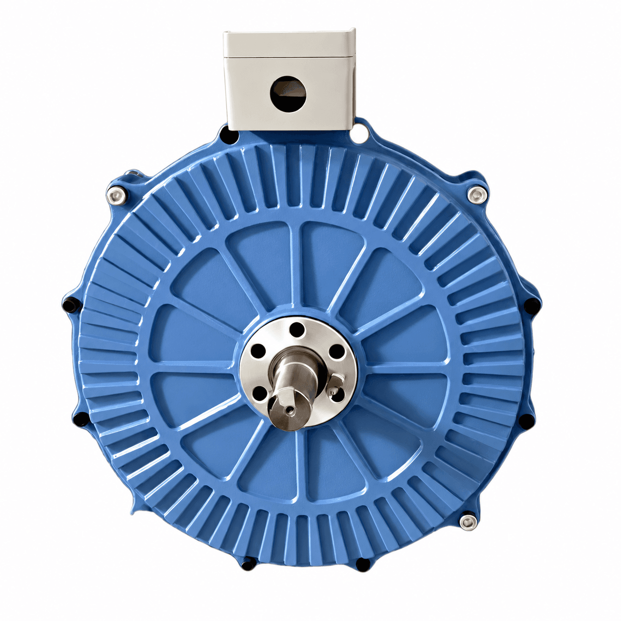
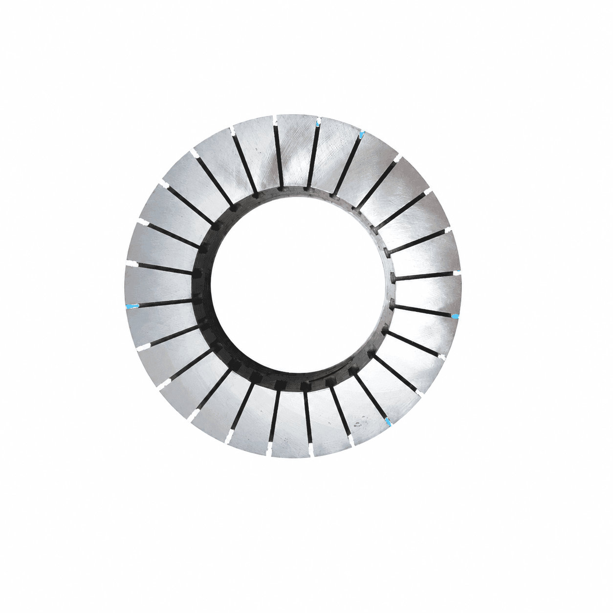
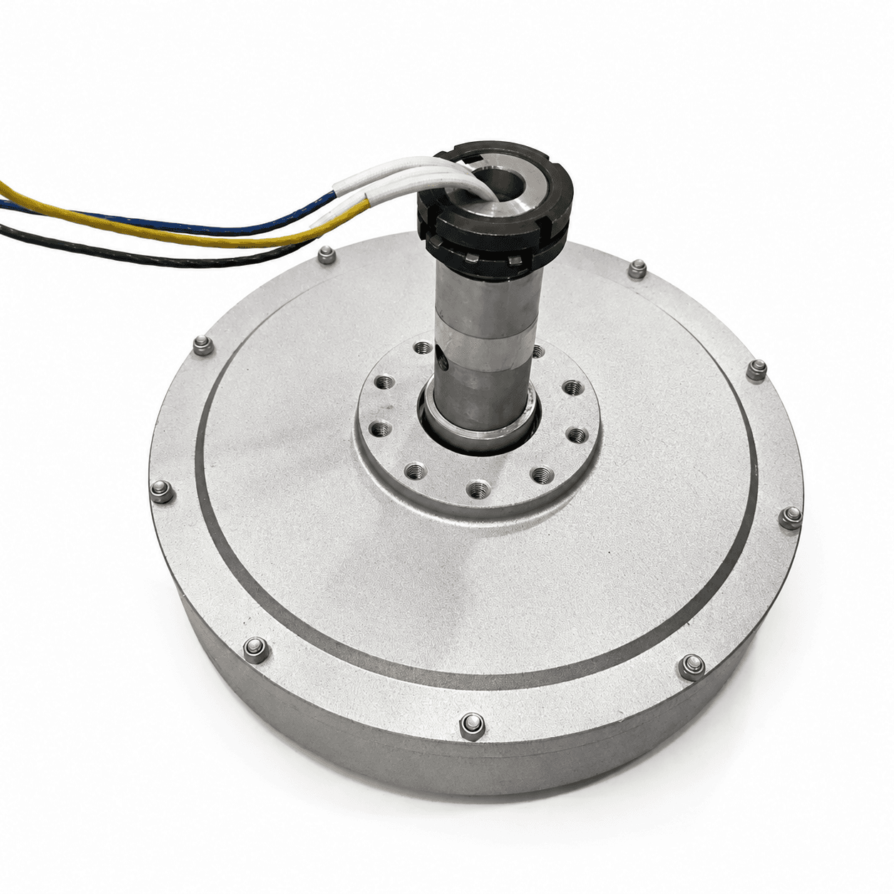
Supplier reference photography supports appearance review. Actual drawings and acceptance tests define your program.
Before the first drawing
No. Share your envelope and duty cycle. We can discuss single-sided, dual-rotor, iron-core, coreless and PCB approaches, with trade-offs reviewed for your project.
Yes. Identify the build-to-print scope, drawing revision, materials and acceptance tests. We will clarify design responsibility and the required manufacturing route.
It is a planning target for suitable programs after DFM approval, material availability, drawing freeze and order confirmation. Special tooling, magnet grades or validation can extend it. The quotation confirms the schedule.
Request an NDA in your brief. We will agree the confidentiality terms and a drawing-transfer channel before you share confidential files. You can attach a non-confidential STEP/PDF and your NDA template. Confidential drawings require an existing signed agreement; submitting a request does not sign it.
Let’s start with the constraint